


XeVision HID lighting system installation information -
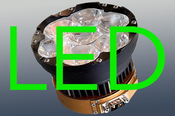
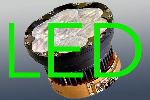
Check LED lighting fixture installation here
- - HID lighting system installations by certified professional shops (and help on 337 approvals)
- - Installation Instructions
- - HID conversion kit generic wiring diagram
- - HID amperage load
- - XePulse™ modules wiring recommendations
- - Input power wiring for the super-thin XeStrike™ ballast, XV4D SPM & XV4D DPM
- - Installation example in Glasair I RG
- - Installation example by Embry-Riddle Aeronautical University in Prescott (AZ)
- - Various customer installation photos and testimonials
Please contact the shop, which is closest to your location or a preferred FSDO. Competent maintenance technicians have experience with our XeVision HID system installations and 337 approval procedures. The list below shows the involved FAA FSDO's, shop and contact person, examples of installations with approved FAA 337 field approval documents. Please check thelist of selected approved FAA 337 by clicking here.
Philadelphia FSDO
Hortman Aviation, Philadelphia, PA
Herbert Hortman
(215) 969-0311
Grumman Tiger, Yankee, Traveller Piper Cherokee
12 or more
South Bend SBN-FSDO
Excel-Air Services, Rensselaer, IN
John Sjaardema
(888) 91-EXCEL
Grumman Tiger, Cheetah, Traveller Cessna 182
6 or more
Oakland OAK-FSDO
Top Gun Aviation, Stockton, CA
Thomas Rouch
(209) 983-8082
Mooney
Grumman Tiger
Soccata Tobago
Piper PA-235
10 or more
Minneapolis FSDO
Sierra Hotel Aero, St. Paul, MN
Chris Gardner
(651) 306-1456
www.navion.com
Navion (OEM) Piper Mirage
Beech Baron
10 or more
DuPage DPA-FSDO
Motive Services Co, Algonquin, IL
Lynn Hadler
(847) 428-4242 office
(847) 565-6589 cell
Yak 52
Grumman
Cessna
Mooney M-20J
12 or more
Oakland OAK-FSDO
Oakland Aircraft Maintenance, Oakland, CA
Bill Putney
510-638-5198
Navion
Cessna
Grumman
Mooney
12 or more
Detroit AGL-FSDO
Avantgarde Aviation, Waterford, MI
John Johns
(248) 666-3730
Beech M-35, Baron, Bonanza T-tail Lance
5 or more
Las Vegas FSDO
Classic Aero LLC, Ramona, CA
(760) 496-8723
Cessna P-210
Grumman
3 or more
Spokane FSDO
Southfield Fuel / Heli-Prop Aviation Coeur D'Alene, ID
Larry Booher
(208) 772 6404
Mooney
1 or more
Philadephia FSDO
Schaerer Aviation, Lebanon, PA
Grumman
1 or more
Oakland OAK-FSDO
Aeroventure, Petaluma, CA
Peter Bradley
(707) 778-6767
Piper PA-28R-200
1 or more
Boston FSDO
GJ Aviation,
KFXE Fort Lauderdale Executive Airport
5115 NW 98th Drive
Coral Springs, FL 33076
Glenn E. Juber, A P/IA/CFI
cell: 860-208-7953
fax: (754) 484-4273
Mooney M20F, M20J Piper Archer Piper Geronimo Apache, Aztec Cessna 500/501, 550, 560 series Citation Cessna T337
5 or more
Van Nuys FSDO
Light Helicopter Depot, Santa Paula, CA
Dan Casey
(650) 224 0802
Robinson R22, R44
in the works
Harrisburg PA FSDO
Advanced Aircraft Services, Lancaster, PA
Jim Mazzante, A P
(717) 735-5179
Diamond Aircraft DA40 Cirrus SR-20, SR-22 in the works:
3 or more
Australia Sydney
Bilyara Maintenance and Engineering
Garth Bartlett
(612) 9532-1757
Cessna, others
Saint Paul MN
FSDO
Modern Aero Inc., Saint Paul, MN
Frank Nook, Avonics
(952) 941-6255, ext. 106
Diamond Aircraft DA42 TwinStar
1 or more
Los Angeles
CA
FSDO
Security Aviation, Hawthorne, CA 90250
Chris Miller
(310) 978-1095
Diamond Aircraft DA40
3 or more
Top
A complete installation manual is provided with each XeVision kit.
Download a copy of the installation manual.
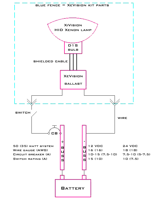
Below is an example of a typical 12 VDC installation. The existing aircraft (a/c) switch, CB, and wiring may be used if the electric rating is equal and higher than 10 A. We like to see 18 awg or 16 awg wires. For new installations please follow the diagram below.
Top
There are two distinct XV4D ballast models:
SPM: Single power mode with setup for one single-output power, like 35 W or 50 W
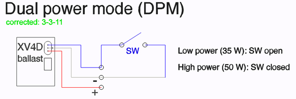
DPM: Dual power mode allowing switching between the preset dual output power setting
The input power connectors of the two models are wired differently. The input connector consists of three pins with + power, ground, and trigger. Please see the wiring diagrams below representing SPM and DPM model required wiring.
XV4D ballast models power input wiring
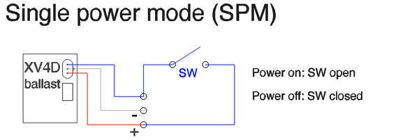
Note:
Electrical wiring diagrams of SPM and DPM models are different.
SPM standard on/off wiring with a two-pin connector (or open trigger wire) is shown in the generic HID wiring diagram here. SPM remote on/off switching (SW) is done between + power (red) and control wire (white)
DPM is remotely switched by SW is between trigger wire (white) and ground wire (black) to select
35 W or 50 W. on/off switching is done by a switch (and CB) in the + power (red) wire.
Note:
Please click on the thumbs for a larger wiring diagram or download the DPM diagram and SPM diagram
Top
For the circuit breaker values the maximum inrush current at start-up needs to be considered.
This may be larger than the recommended CB value for the wire protection.
If a CB value is marginal, start-up of the HID bulb may fail.
For 50 watt systems
12 VDC
24 VDC
Ballast steady state current (A)
4.6
2.3
Wire gauge (AWG) recommended (depends on length)
16
18
Circuit breaker (A) recommended
10 - 15
7.5 - 10
For 35 watt systems
12 VDC
24 VDC
Ballast steady state current (A)
3.2
1.6
Wire gauge (AWG) recommended (depends on length)
16
18
Circuit breaker (A) recommended
7.5 - 10
5 - 7.5
Top
This is our new solid-state module which is designed for our XeStrike™ D-series ballasts with three input pins. Please check the XePulse™ 2 page for XePulse™ 2 description and specifications.
To get all XePulse™ 2 related documents, please go to the download page.
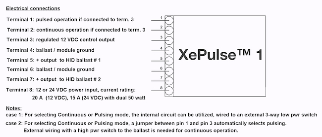
You may download this diagram as a pdf file here
External switching example - wiring diagram for a Grumman Traveller
Here is an example of an external switching wiring diagram for our pulsing system by Al Griffin for his Grumman Traveller, N7284L, prepared for the FAA 337 application. Download the pdf file of this nice wiring diagram.
This wiring example can be applied to other similar XeVision HID system installations. Thanks Al for providing and sharing this valuable information. For Al's complete FAA 337 click here.
XePulse™ 1 D+ with XV4D (left) and XV3D (right) ballast special wiring


Top
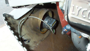
XeVision H.I.D. lamp installed in Glasair RG I
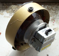
XeVision H.I.D. lamp installed in Glasair RG I

XeVision H.I.D. lamp installed in Glasair RG I

XeVision H.I.D. lamp installed in Glasair RG I
We got a fleet approval with FAA form 337 for our certified aircraft from the Scottsdale, AZ FSDO.
The pictures show how we attached everything to an aluminum plate and used existing mount holes in the nose bay of the aircraft and aircraft wiring. We did have to use the noise suppressors for this installation. They were done back in July and August 2003 and have given us excellent service with NO defects or failures of any kind.
Pat Kelly
Chief Inspector
Embry-Riddle Aeronautical University
Prescott, AZ Campus
The picture example below shows the professional installation in a PA44-180 of their fleet.


Top
For Diamond Aircraft DA40 aircraft XeVision HID installations
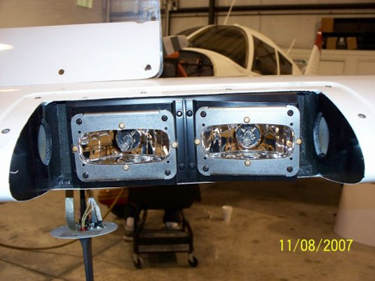
Dual XeVision XV-19-W installation in Diamond Aircraft DA-40
Download a great DA40 - XeVision HID light installation manual kindly provided by DiamondAviator.org. This installation manual is detailed with plenty of instructional photos.